Transformers Tested with the PMT Pulses at -40oC
N. Kitamura October 10, 2003
_________________________________________________________
Read LeCroy scope data:


Objectives
(1) Compare the passive base with different transformers: one with the RG178 coax transformer ("Old Xfmr") and one with the new bifilar transformer ("New Xfmr").
(2) Study the effects of the RC filtering at the HV entry to the passive base.
Procedure
Base A:
Old Xfmr (RG178 coax transformer that is part of the EMCO 9731C passive base upon delivery).
The output coaxial cable is bottom entry with the center conductor making an arc above the board.
Base B:
New Xfmr (22AWG, 10KV, silicone-insulated wire, bifilar winding, replacing the transformer on the EMCO 9731C passive base.)
The output coaxial cable is side-entry with a minimum excursion of the center conductor before attaching to the Xfmr.
See separate document for more detailed description of the transformers.
The method of attachment of the RG180 coaxial cable to the transformer secondary was different for the two boards. See accompanying figures.
A 50W resister was inserted between the end of the RG180 coaxial and the 50W scope input channel.
Base A and Base B were each attached to a Hamamatsu R7081-02 PMT operating at -40C. The HV was supplied from rack-mount laboratory supplies. The HV was adjusted so that both PMTs had a gain of approximately 1 x 10⁷.
Curves obtained by averaging over 1000 triggers are presented here. The curves represent average over the distribution of all PE levels at -40C.
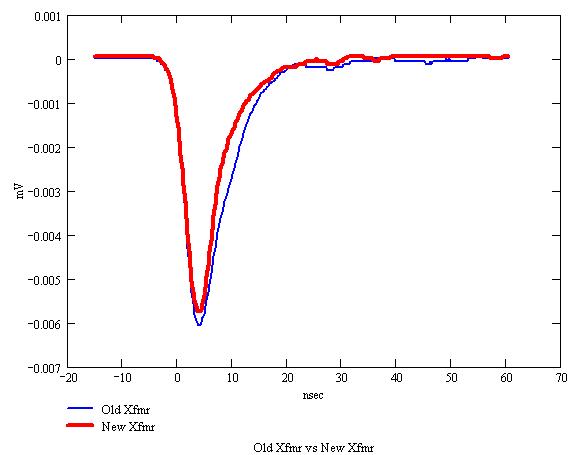
Comparison of New Xfmr and Old Xfmr
Old Xfmr vs New Xfmr
Sampling freq 4 GS/sec
Averaged over 1000 sweeps
Temperature -40C
PMT gain 1 x 10⁷ (approx)
Trigger -1mV
Horiz nsec
Vert mV
The combination of the new transformer and the side-entry cable attachment exhibit a better performance over the combination of the old transformer and the bottom-entry cable attachment.
(This new transformer had no additional RC filtering.)
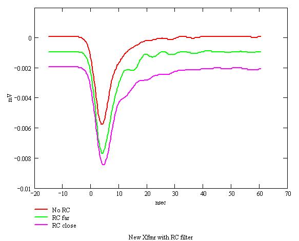
Effects of RC Filtering at HV Entry
It was suggested to add an RC filter at the HV entry point. A combination of a 100kW resistor in series between the HV and the anode and a 2.2nF capacitor spanning the dynode chain was tested.
When the capacitor leads were not minimized, a clear oscillatory behavior was observed ("RC far"). The oscillation frequency was consistent with a resonance due to the 2.2nF and a parasitic inductance of approximately 0.2nH. Clipping the leads and re-mounting the capacitor reduced the oscillations ("RC close"), but, in this case, the pulse had a broader tail than the original pulse.