Transformer Bandwidth Analysis
10/28/2003 Nobuyoshi Kitamura
Objective:
Given the scope shot of the pulse response, determine the bandwidth of the transformer. (We do not have a sine wave source that goes up to sufficiently high frequency. Have only pulse response data.)
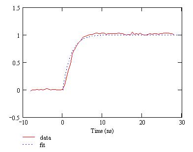
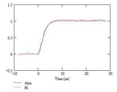
Actual data (18 AWG hookup wire, bifilar, 10 turns):
From the scope shot, the rise time (10-90%) found to be about 4 nsec.
Analytical Model
A naive first-order transfer function does not fit the data very well, as seen below.
Step response ==> invlaplace [ H(s) / s ]
The simple model does not exhibit the inflection point present in the measured response curve.
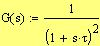
The following second-order transfer function fits data reasonably well.
step response ==> invlaplace [ G(s) / s ]
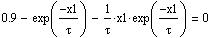
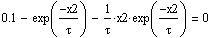
The parameter t was adjusted to make the 10-90% risetime equal to the observed value of 4 nsec.
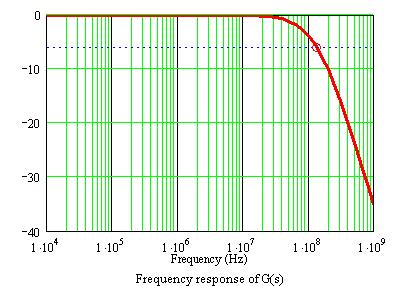
Frequency-Domain Response of G(s)
As seen above, the -6dB cut-off frequency, corresponding to the observed pulse-response, is estimated to be:
Hz
Notice that this value is considerably higher than the reciprocal of the 10-90% risetime (divided by 2p). (It is more related to the 1/e risetime, but not exactly.)
Hz
Conclusion
The bandwidth of the transformer is about 130 MHz.
Hz
Continue on with further analysis...
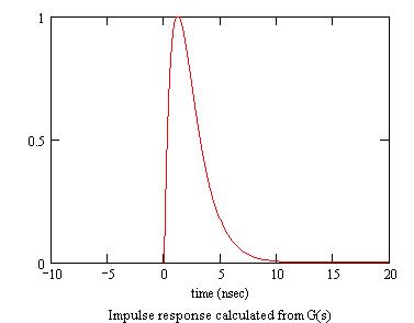
Impulse Response
Assuming that the above model transfer function is valid (it appears to be a good approximation so far), the impulse response is calculated as follows.
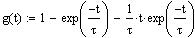
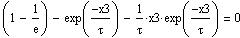
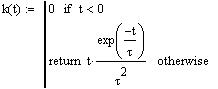
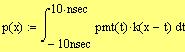
The impulse response function is the inverse laplace transform of G(s):
This function peaks at t = t.
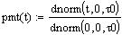
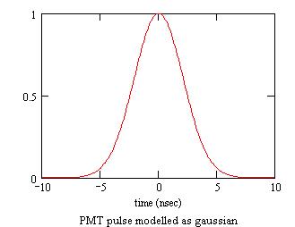
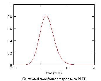
Modelling the PMT Pulse Response of the Transformer
The PMT pulse modelled as gaussian is shown below.
t0 is taken to be one-half of the "anode pulse rise time" given in the PMT spec sheet. (No adjustment.)
Convolution of the computed impulse response of the transformer and the PMT pulse modelled as gaussian is shown below.
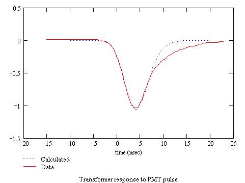
Comparison with data
The model predicts the intilal and the middle portion of the data. The actual data, however, has a longer tail that is unexplained by the model.
Note that the PMT response was measured with the transformer mounted on the HV base board, and we do not have a square-pulse response data for the same setting. The observed long tail is likely due to a secondary parasitic effects related to the transformer mounting method (speculative).