
Click here to
see what happened after the mux output resistors were changed.
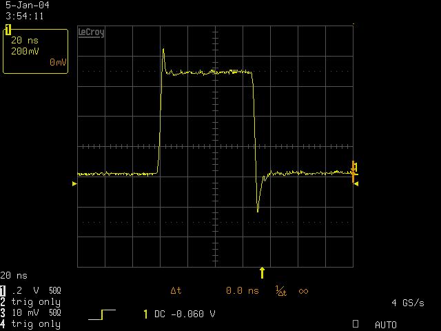
The scope probe has been attached to the flasher board at the connector J1
which goes to the mainboard (to connector J20) - they are small SMB-style
connectors.
The square wave pulse is about 70 ns wide. The flasher board LED settings
have been set to their maxima (brightness and width both set to 127).
Now for the corresponding ATWD current pulse: (approx 3.5ns per bin -
time flows backwards)
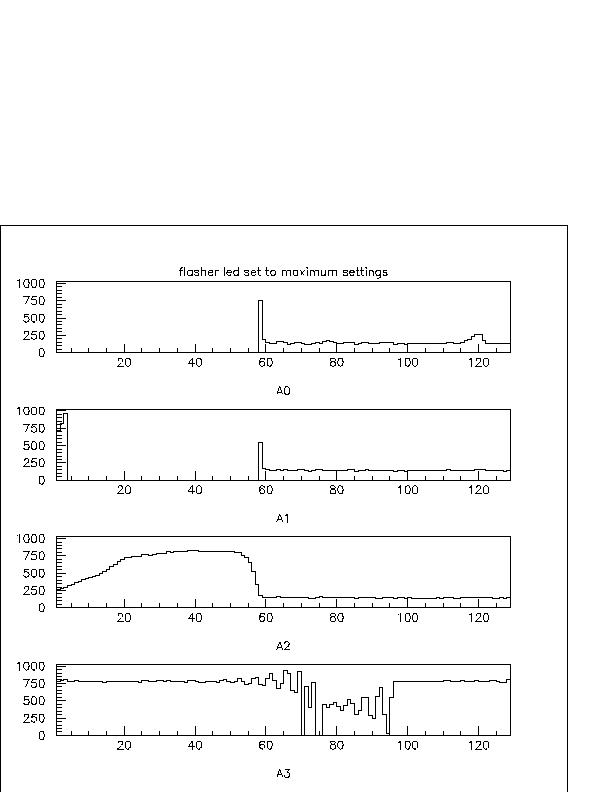
The current pulse almost reaches zero (but doesn't) in the initial downward
spike. There is some 'inverse saturation' during
the ringing later on (where the ATWD values are zero). (the 'pedestal' current
position can be adjusted to avoid saturation at either end (max or min) - this
particular position (around 750 counts) seems to work the best).