Overview
It is designed to remove non-Neutrino oriented but has impulsive pulser event that can be identifiable by the reconstruction methods
Untagged calpulser: Interferometry (AraCorrelator)
Surface event: Interferometry and hit time (AraVertex)
Interferometry will be introduced at the event selection method
All cuts are independant.
Calculated analysis variables by Interferometry are also used to separate signal/background
3rd data cleaning is done by below command:
source ../setup.sh
python3 arr_time_table_maker.py <station ID>                                         # calculates arrivaltime table by ray tracing
python3 script_executor.py -k reco_ele_lite -s <station ID> -r <run number>          # performs vertex reconstruction based on AraCorrelator method
python3 script_executor.py -k rpr -s <station ID> -r <run number>                    # calculates Root Power Ratio for AraVertex based reconstruction
python3 script_executor.py -k vertex -s <station ID> -r <run number>                 # performs vertex reconstruction based on AraVertex method
python3 script_executor.py -k qual_cut_3rd -s <station ID> -r <run number> -b 1 -q 3 # performs 3rd data cleaning
For the simulation side:
source ../setup.sh
python3 sim_script_executor.py -k reco_ele -s <station ID> -d <sim output path>       # both signal and noise. finds c_max of all elevation angle
python3 reco_ele_lite_merge_sim.py <station ID> <signal or noise>                     # both signal and noise. re-structure the vertex reconstruction results by chooing only one c_max
python3 sim_script_executor.py -k rpr -s <station ID> -d <sim output path>            # both signal and noise
python3 sim_script_executor.py -k vertex -s <station ID> -d <sim output path>         # both signal and noise
python3 sim_script_executor.py -k qual_cut -s <station ID> -d <sim output path>       # both signal and noise
It will use filt_qual_cut_loader class
Calpulser cut
Related doc. DB2731
This is done by get_calpulser_surface_events and get_calpulser_cut function
User must run vertex reconstruction first by below command:
source ../setup.sh
python3 arr_time_table_maker.py <station ID>                                         # calculates arrivaltime table by ray tracing
python3 script_executor.py -k reco_ele_lite -s <station ID> -r <run number>          # performs vertex reconstruction based on AraCorrelator method
python3 sim_script_executor.py -k reco_ele -s <station ID> -d <sim output path>       # both signal and noise. finds c_max of all elevation angle
Due to ARA’s trigger algorithm, If DAQ has malfunction, Calpulser signal can have a unexpected timestamp value and will be mixed into RF triggered signal
To remove untagged calibration signal, we reconstructed position of Calpulser signal by interferometry and use it by defining the cut region
Any signal that reconstructed position is inside of Calpulser reco. region, it will be excluded from dataset
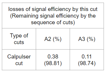
Fig. 76 live time losses by calpulser cuts
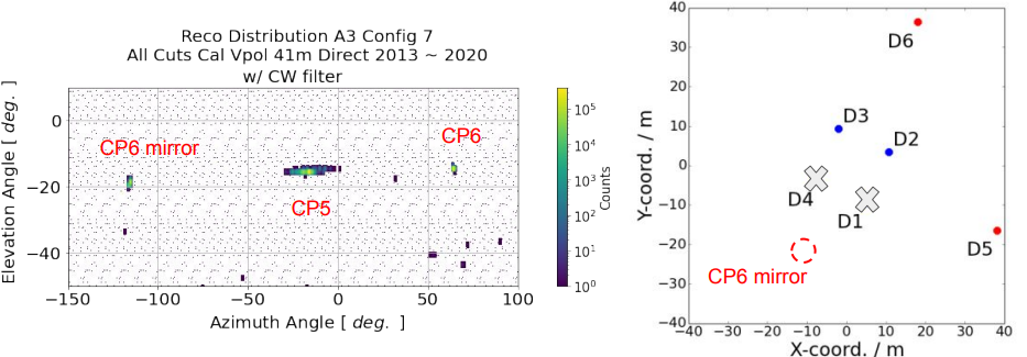
Fig. 77 knwon calpulser example
A2 Calpulser
From 2018, transmitter is switched to CP 5 string
CP 5 mirror position on config 5 is gone on 2018
From 2020, Calpulser reco. results are spreaded out because string 1 is excluded by duplication
By including 1st block into analysis, reco. results can be secured without string 1
1st block offset issue can be corrected by 1) excluding it from ZeroMean correction and 2) apply band-pass filter
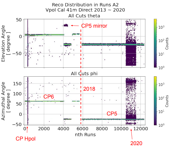
Fig. 78 A2 calpulser distribution
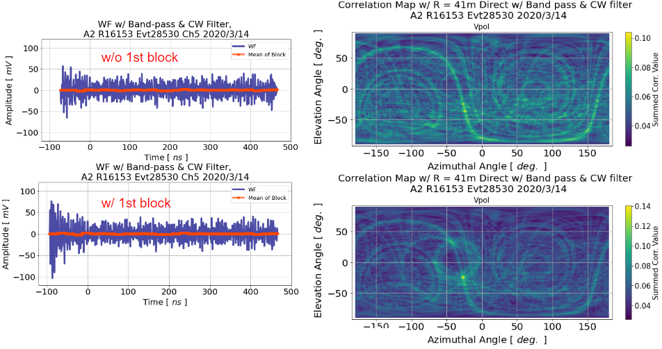
Fig. 79 A2 calpulser reconstruction by including 1st block with band pass filter
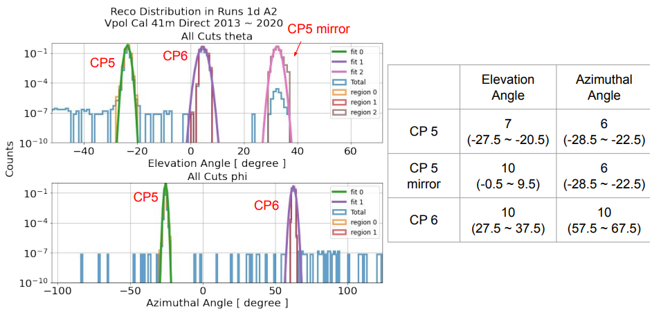
Fig. 80 A2 calpulser results

Fig. 81 A2 calpulser distriution and cut results in elavation vs azimuth angle space
A3 Calpulser
From middle of 2019, transmitter is switched to CP 5 string
On 2019, Due to loss of 2 strings (D1 : dead bit, D4: duplication), We losses azimuthal sensitivity.
two elevation/azimuth position for CP 6
more wide distribution of CP 5
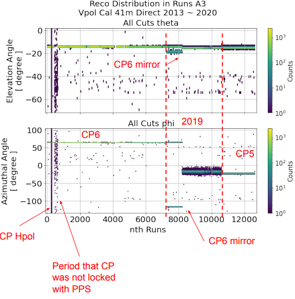
Fig. 82 A3 calpulser distribution
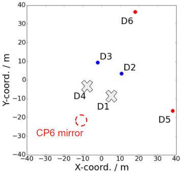
Fig. 83 Expected A3 calpulser mirror position on 2019 data set
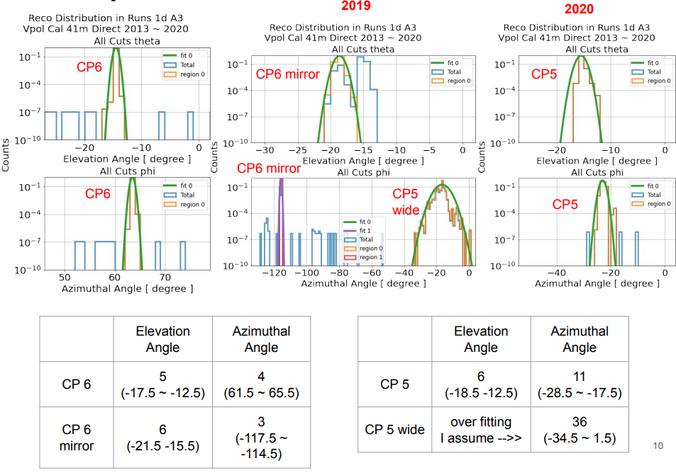
Fig. 84 A3 calpulser results
Fig. 85 A3 calpulser distriution and cut results in elavation vs azimuth angle space. Due to resolution of 1 degree, calpulser distribution in config7 is appeared to be outside of cut.
Surface cut
This is done by get_calpulser_surface_events function
User must run 2 vertex reconstructions first by below command:
python3 arr_time_table_maker.py <station ID>                                         # calculates arrivaltime table by ray tracing
python3 script_executor.py -k reco_ele_lite -s <station ID> -r <run number>          # performs vertex reconstruction based on AraCorrelator method
python3 script_executor.py -k rpr -s <station ID> -r <run number>                    # calculates Root Power Ratio for AraVertex based reconstruction
python3 script_executor.py -k vertex -s <station ID> -r <run number>                 # performs vertex reconstruction based on AraVertex method

python3 sim_script_executor.py -k reco_ele -s <station ID> -d <sim output path>       # both signal and noise. finds c_max of all elevation angle
python3 reco_ele_lite_merge_sim.py <station ID> <signal or noise>                     # both signal and noise. re-structure the vertex reconstruction results by chooing only one c_max
python3 sim_script_executor.py -k rpr -s <station ID> -d <sim output path>            # both signal and noise
python3 sim_script_executor.py -k vertex -s <station ID> -d <sim output path>         # both signal and noise
AraCorrelator Surface cut
This cut is set by reconstructed zenith (or elevation) angle and depth
Any signal that reconstructed ele. angle is over 35 degree or depth is over 0 m, it will be excluded from dataset
Elevation angle 35 degree at the radius 300 m is close to 1) air/ice transition boundary and 2) beginning of shadow region
If reconstructed position is outside of 300 m, event is excluded by depth
Zenith Cut: > 35 deg
Z Cut: > 0 m (in A3, > -1.5 m)
AraVertex Surface cut
Reconstructed position is based on hit (arrival of ray) time identified by Root Power Ratio (RPR) value of each channel
Any signal that reconstructed ele. angle is over 35 degree or depth is over 60 m, it will be excluded from dataset
RPR is calculated by partial region (25 ns) of WF. So, It is relatively free from noise interference than interferometry
Cons. is, it is not taking into account similarity between channels
Zenith Cut: > 35 deg
Z Cut: > 60 m
Fig. 86 live time losses by 4 surface cuts
Fig. 87 4 surface cuts example
Fig. 88 4 surface cuts example in sequence