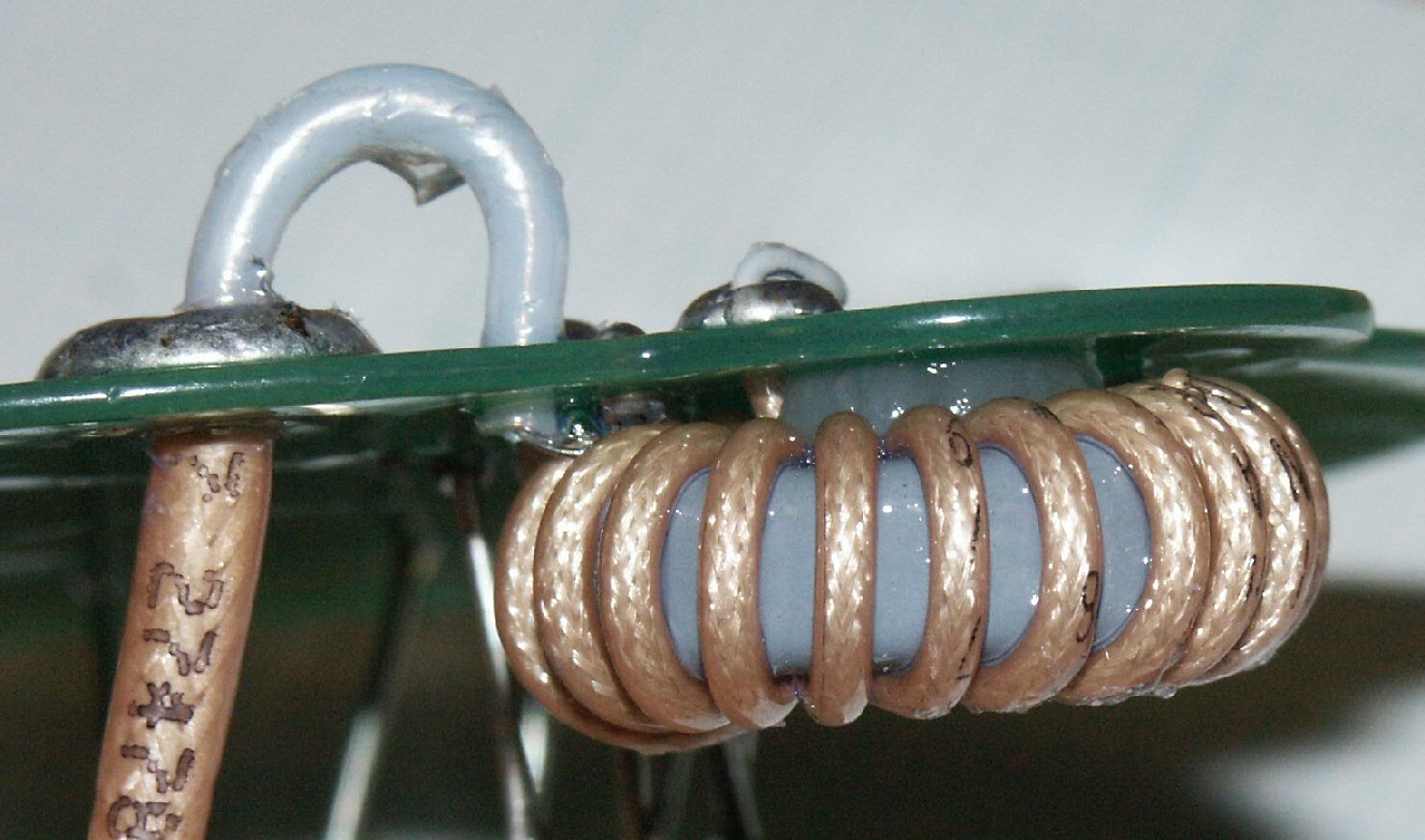
In the IceCube DOM, the PMT cathode is at ground potential, and, as a result, the PMT pulse from the anode must be ac-coupled to the signal processing unit (i.e., the Main Board). The ac-coupling device, whether it is a transformer or a capacitor, must withstand the maximum anode-to-cathode voltage of 2000VDC and allow the fast PMT pulses to pass through without distortion. Transformer coupling is preferred to capacitor coupling, as discussed by Jerry Przybylski (link). The toroidal transformer that uses RG174 cable for the winding was found to exhibit desirable pulse-transfer characteristics; however, it had a shortcoming that RG174 has a maximum operating voltage of only 1000Vrms (c.f., Action Item PDR-4 "Coax Negative Margin"). The present work establishes that an alternative toroidal transformer design employing a bifilar winding of silicone-insulated wire to have a sufficient voltage margin and pulse-transfer characteristics.
Alternative design work presentation demonstrates that a bifilar toroidal transformer can achieve a pulse-transfer characteristics comparable to that of a coaxial toroidal transformer.
Study on the effects of the low temperature concludes that changing the temperature from RT to -30C results in a pulse-height attenuation by approximately 6%, presumably due to the decreased permeability of the toroidal core.
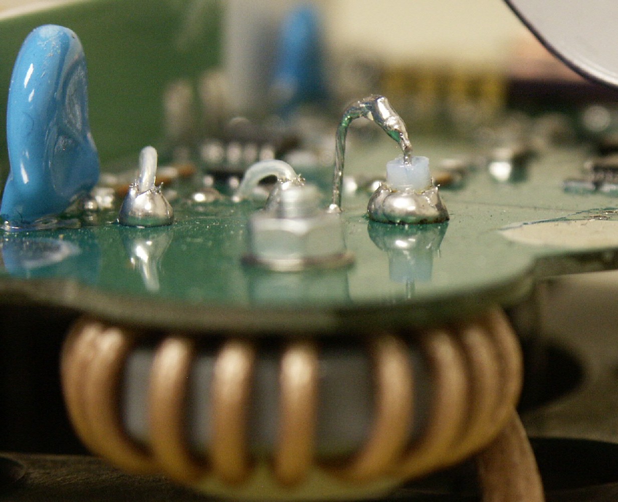
Combined performance of the two types of the transformers (coaxial vs bifilar), the passive base board, and the method of output cable attachment in response to the PMT noise pulses has been measured at -40. See the results. The bifilar transformer with a laterally attached output cable clearly outperforms the coaxial transformer with a bottom-entry output cable.
The bifilar transformer proposed for the next design.
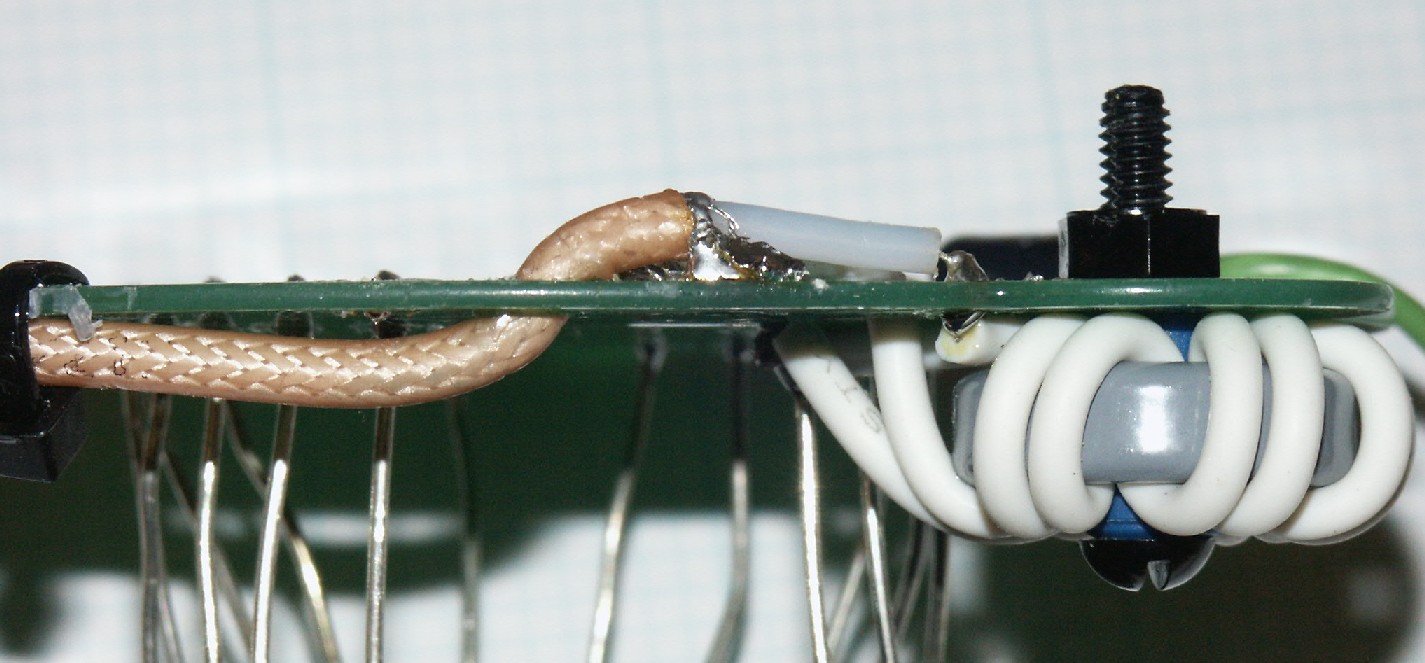
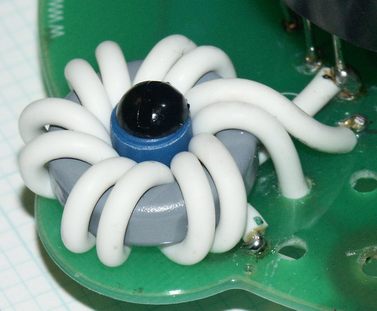
Silicone-insulated bifilar winding (22 AWG 7/30 stranded; 0.110" OD; 40 mils insulation; 10kV; 150C; Harbour Industries, Inc., Cat #BSR3239-2210, or, equivalent), 5 and 1/2 turns, on a toroidal core (22mm OD, 6mm H, mi=15000 (nom.); Magnetics, Inc., Cat # ZH42206-TC, or equivalent). The winding is retained by inserting a short plastic tubing (shown here is a segment of a Bic ballpoint pen cap).
It is crucial to keep the bifilar pair close together throughout the winding, rather than spacing the wires evenly apart.
Increasing the number of turns by overlapping the windings or by using a larger core does not improve the pulse-transfer characteristics.
The bandwidth of the transformer, estimated from the pulse-response data, is about 130MHz.
Summary of the specifications for the transformer is found here.